

In fiber optic networks, engineers normally try to minimize signal loss. However, more optical power is not always better.
When a short fiber link, high-output transmitter or optical amplifier delivers excessive power to a receiver, the receiver may enter its overload region. This can increase bit errors, destabilize the connection or, in extreme cases, exceed the optical input rating of the equipment.
A fiber optic attenuator intentionally introduces a controlled amount of optical loss so that the received signal remains within the equipment’s acceptable operating range.
Fiber attenuators are commonly used for:
- Protecting receivers from optical overload
- Adjusting power in short fiber links
- Testing receiver sensitivity and optical margins
- Balancing optical power in PON or WDM systems
- Simulating fiber and component loss
- Controlling input or output power in amplified optical systems
Selecting an attenuator requires more than choosing a value such as 5 dB or 10 dB. Wavelength, fiber type, connector polish, return loss, attenuation tolerance and maximum optical power must all match the application.
What Is a Fiber Optic Attenuator?
A fiber optic attenuator is a passive optical component that introduces a controlled reduction in optical signal power within a fiber transmission line. ITU-T G.671 defines an optical attenuator as a passive component that produces controlled signal attenuation in an optical fiber transmission system.
Attenuation is expressed in decibels:
- A 1 dB attenuator produces a relatively small power reduction.
- A 5 dB attenuator reduces the signal more substantially.
- A 10 dB attenuator reduces optical power by a factor of ten.
- A 20 dB attenuator reduces optical power by a factor of one hundred.
An attenuator does not change the data rate, modulation format or network protocol. Its purpose is simply to reduce optical power in a controlled and predictable manner.
It also does not improve optical signal-to-noise ratio. In an ideal attenuator, signal and optical noise are both reduced. The device is used to place the signal within the receiver’s operating range, not to repair a poor-quality signal.
Why Are Fiber Optic Attenuators Needed?
1. Preventing Receiver Overload
Every optical receiver has an acceptable input-power range.
Two important limits are:
- Receiver sensitivity: the minimum input power required to achieve the specified performance or bit-error rate.
- Receiver overload: the maximum input power at which the receiver can still operate correctly.
If received power is below sensitivity, the link may experience errors or fail. If it is above the overload limit, the photodetector and receiver electronics may saturate.
Receiver sensitivity and overload are therefore both important parameters when calculating the optical link budget. VIAVI identifies them as primary receiver specifications used in optical transceiver testing.
A correctly selected attenuator reduces excessive power while keeping the signal safely above the receiver sensitivity limit.
2. Compensating for Very Short Links
Optical transceivers are often designed with enough launch power to support their maximum specified link distance.
When the same transceiver is used across only a few meters of fiber, the link loss may be too low. The receiver can consequently receive more power than intended.
This situation is particularly relevant to:
- Long-reach transceivers used over short distances
- Laboratory connections
- Equipment connected within the same rack
- High-output CATV systems
- Links containing optical amplifiers
An attenuator can add the loss that the physical link does not naturally provide.
3. Testing Receiver Sensitivity
A variable optical attenuator is commonly placed between a reference transmitter and a receiver under test.
The attenuation is gradually increased until the receiver reaches a defined bit-error-rate threshold. The corresponding received power is then used to determine receiver sensitivity. VIAVI describes this VOA-based configuration as a standard receiver-sensitivity measurement method.
4. Simulating Link Loss
During system development or acceptance testing, engineers may need to simulate:
- Longer fiber spans
- Connector loss
- Splice loss
- Splitter loss
- Aging margin
- Degraded link conditions
A VOA allows loss to be introduced without physically adding long cable spools or multiple passive components.
5. Optical Power Balancing
Attenuators may be used to reduce excessive power in selected paths or wavelength channels.
Examples include:
- Point-to-multipoint branches with unequal path losses
- Laboratory WDM systems
- DWDM test platforms
- CATV distribution branches
- Optical switching and monitoring systems
ITU-T L.31 identifies receiver overload prevention, PON branch balancing and optical-system measurements as representative attenuator applications.
In operational DWDM networks, channel-level power equalization may also be performed by integrated VOAs, wavelength-selective switches or dynamic gain-control equipment rather than individual connector-style attenuators.
Fixed vs. Variable Fiber Optic Attenuators
Fiber attenuators are primarily divided into fixed and variable types.
Fixed Fiber Optic Attenuator
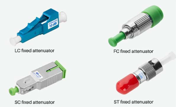
A fixed attenuator provides one predetermined attenuation value.
Common nominal values include:
- 1 dB
- 2 dB
- 3 dB
- 5 dB
- 10 dB
- 15 dB
- 20 dB
Available values vary by manufacturer and product family.
Advantages
- Compact construction
- No power supply required
- Stable attenuation
- Simple installation
- Relatively low cost
- Suitable for permanent deployment
Typical Applications
- Receiver overload protection
- Short optical links
- FTTH and PON troubleshooting
- CATV distribution
- Telecom equipment interfaces
- Permanent link-power adjustment
Fixed attenuators are generally appropriate when the required attenuation value is already known and is not expected to change.
Variable Optical Attenuator
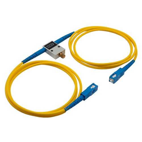
A Variable Optical Attenuator, or VOA, allows attenuation to be adjusted across a specified range.
Adjustment may be:
- Manual
- Motorized
- Electrically controlled
- MEMS-based
- Continuously variable
- Adjustable in discrete steps
ITU-T L.31 recognizes both continuously variable and step-adjustable designs, as well as mechanical and electrically controlled implementations.
Advantages
- Adjustable loss
- Precise optical-power control
- Suitable for automated testing
- Useful for sensitivity and margin measurements
- Can simulate changing link conditions
- Supports dynamic power balancing
Typical Applications
- Receiver-sensitivity testing
- BER testing
- Optical-margin analysis
- Component characterization
- Production testing
- WDM power balancing
- Automated laboratory systems
EXFO lists BER testing, loss simulation, optical-margin analysis, system characterization and WDM power balancing among the principal applications of multi-channel VOAs.
Common Attenuator Form Factors
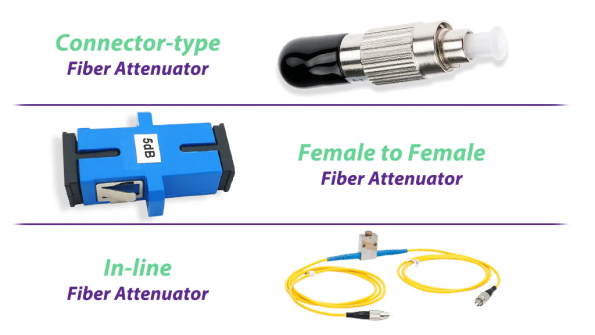
1. Plug-Type Attenuator
A plug-type attenuator normally has:
- A male connector on one side
- A female receptacle on the other side
Examples include:
- LC male to LC female
- SC male to SC female
- FC male to FC female
It can be plugged directly into an equipment port or adapter, after which the patch cable is connected to the female side.
Advantages
- Compact
- Easy to install
- No splicing required
- Suitable for equipment-side attenuation
- Easy to remove or replace
The male-to-female optical pad is one of the most widely used fixed-attenuator configurations because it can be inserted without modifying the rest of the fiber plant.
2. Adapter-Type Attenuator
An adapter-style attenuator usually has female interfaces on both sides.
It can be installed in:
- Patch panels
- Adapter panels
- Distribution frames
- Test setups
The connector type and polish must match both mating patch cords.
3. In-Line Attenuator
An in-line attenuator is integrated into a fiber assembly.
It may be supplied as:
- A connectorized patch cable
- A pigtail
- A bare-fiber component
- A splice-in module
In-line designs are useful for permanent installations and customized optical assemblies.
ITU-T L.31 refers to attenuators with attached fibers as attenuating patch cords and notes that unconnectorized versions may be spliced directly into the link.
4. Benchtop or Rack-Mount VOA
Laboratory and production VOAs may include:
- Digital attenuation setting
- Integrated optical power meters
- Multiple optical channels
- Remote Ethernet or USB control
- Automated power-level control
- SCPI command support
These systems are designed for repetitive measurements, production testing and automated optical-component characterization.
Single-Mode vs. Multimode Attenuators
Fiber mode must match the network.
Single-Mode Attenuator
Single-mode attenuators are commonly designed for wavelengths such as:
- 1260–1620 nm
- 1310 nm
- 1490 nm
- 1550 nm
- C-band or L-band
They are used in:
- Telecom networks
- FTTH and PON
- CWDM and DWDM
- CATV systems
- Single-mode transceiver testing
Multimode Attenuator
Multimode attenuators are designed for multimode fiber systems, typically operating around:
- 850 nm
- 1300 nm
Multimode attenuation can be affected by the distribution of optical modes launched into the fiber. A properly designed multimode VOA should therefore provide stable attenuation under different mode-fill conditions. EXFO distinguishes its single-mode MEMS implementation from a multimode neutral-density-filter design optimized for mode-independent attenuation.
A single-mode attenuator should not be substituted for a multimode attenuator merely because the connector fits mechanically.
How Does a Fiber Optic Attenuator Work?
Different attenuator designs use different physical mechanisms.
These may include:
- Absorptive materials
- Neutral-density filters
- Controlled fiber misalignment
- Air-gap adjustment
- Microbending
- Beam displacement
- MEMS structures
- Polarization-based optical control
The implementation depends on whether the component is fixed, manually adjustable, electronically controlled, single-mode or multimode.
A well-designed attenuator should provide controlled loss while minimizing:
- Back reflection
- Wavelength dependence
- Polarization dependence
- Attenuation drift
- Additional modal disturbance
The operating principle is normally less important to the purchaser than the verified optical specifications.
Key Specifications
Nominal Attenuation
Nominal attenuation is the intended amount of optical loss.
Examples include 3 dB, 5 dB or 10 dB.
The actual measured attenuation may differ slightly from the nominal value.
Attenuation Tolerance
Tolerance describes the permitted difference between nominal and actual attenuation.
For example, a nominal 5 dB attenuator with a stated tolerance of ±0.5 dB may produce an actual attenuation between 4.5 and 5.5 dB.
Tolerance is product-specific and should not be assumed to be the same for every attenuator value.
Operating Wavelength
Attenuation may vary with wavelength.
Confirm whether the attenuator is designed for:
- 850 nm
- 1310 nm
- 1490 nm
- 1550 nm
- 1625 nm
- A broad 1260–1620 nm range
- CWDM or DWDM bands
- A specialty wavelength
An attenuator intended for 1550 nm should not automatically be assumed to provide the same nominal loss at 850 nm.
Wavelength-Dependent Loss
Wavelength-dependent loss describes how much the attenuation changes across the specified wavelength range.
Low wavelength dependence is particularly important in:
- CWDM systems
- DWDM systems
- Broadband PON links
- Test and measurement
- Multi-wavelength amplifiers
Return Loss
Return loss indicates how little optical power is reflected back toward the source.
A higher return-loss value indicates lower back reflection.
Low reflection is important for:
- Laser transmitters
- Analog optical systems
- CATV
- PON
- Coherent and measurement systems
APC connectors generally provide better reflection performance than UPC connectors, but both sides of the connection must use the same polish type.
UPC and APC connectors must not be directly mated.
Polarization-Dependent Loss
Polarization-Dependent Loss, or PDL, describes the change in attenuation as the input state of polarization changes.
Low PDL is important in:
- DWDM networks
- Coherent optical systems
- Polarization-sensitive measurements
- Laboratory systems
Maximum Optical Input Power
Every attenuator has a maximum permissible input power.
The required rating depends on:
- Continuous-wave or modulated operation
- Wavelength
- Connector condition
- Attenuation mechanism
- Housing design
- Ambient temperature
Standard telecom plug attenuators should not automatically be used in high-power EDFA or fiber-laser systems.
ITU-T L.31 includes optical-power linearity among the fundamental attenuator parameters and notes that power handling must be verified without permanent damage to the attenuating region.
Environmental Stability
For outdoor, industrial or telecom installations, check:
- Operating temperature
- Storage temperature
- Humidity resistance
- Vibration
- Mechanical endurance
- Attenuation drift
ITU-T identifies mechanical endurance, vibration, cold, dry heat and damp heat among the relevant environmental and mechanical characteristics of fixed attenuators.
How to Calculate the Required Attenuation
The approximate received power without an attenuator is:
Received power = Transmitter output power − Existing link loss
The required attenuation is then:
Required attenuation = Received power without attenuator − Target received power
Example
Assume:
- Transmitter output: +3 dBm
- Existing fiber and connector loss: 2 dB
- Desired receiver input: −5 dBm
Received power without an attenuator:
+3 dBm − 2 dB = +1 dBm
Required attenuation:
+1 dBm − (−5 dBm) = 6 dB
A nominal 6 dB attenuator would place the expected receiver input near −5 dBm.
Before selecting it, also confirm:
- Receiver sensitivity
- Receiver overload limit
- Attenuator tolerance
- Transmitter power variation
- Aging and temperature margin
- Connector and splice losses
Whenever possible, measure the actual received power with an optical power meter rather than relying only on nominal datasheet values.
Where Should the Attenuator Be Installed?
A fixed attenuator is commonly installed near the receiver.
This provides several advantages:
- The receiver input can be measured locally.
- The attenuator is accessible for replacement.
- Excess power is controlled immediately before the receiver.
- The transmitter side does not require remote monitoring.
ITU-T L.31 notes that attenuators are normally inserted at the receiving end of a link for this reason.
The correct location may differ in laboratory, amplified or multi-channel systems, so the complete optical design should still be reviewed.
Common Applications
Optical Transceiver Protection
Fixed attenuators are installed when the calculated or measured receiver power exceeds the module’s overload specification.
FTTH and PON Networks
Attenuators may be used during commissioning, testing or exceptional cases where a branch delivers excessive receiver power.
They should not replace proper splitter design and optical-budget planning.
CATV Distribution
High-output CATV transmitters and EDFAs may require attenuation to establish the correct receiver level at nodes or distribution branches.
The attenuator must have adequate power handling and return-loss performance.
DWDM and CWDM Systems
VOAs may be used to control individual channel power during:
- Laboratory testing
- Amplifier characterization
- Channel equalization
- Optical-margin verification
In live networks, integrated dynamic power-control devices may be preferable to multiple plug attenuators.
Optical Transceiver Testing
VOAs are used to measure:
- Receiver sensitivity
- Receiver overload
- BER performance
- Loss-of-signal thresholds
- Optical margin
EDFA Testing
High-power VOAs may be used to control EDFA input or output during testing.
This requires a device specifically rated for the optical power involved. The designer must also consider ASE, OSNR and amplifier saturation rather than only total power.
Common Selection Mistakes
Choosing Attenuation Without Measuring Power
Selecting 5 dB simply because it is a common value may leave the receiver overloaded or reduce the signal below sensitivity.
Ignoring Wavelength
The nominal attenuation at 1550 nm may not equal the attenuation at 850 nm.
Mixing UPC and APC
The connectors may physically enter an adapter, but the different end-face geometries can cause high loss, reflection and permanent damage.
Using a Single-Mode Attenuator in a Multimode Link
The result may depend strongly on launch conditions and may not provide the expected attenuation.
Exceeding the Power Rating
A standard fixed attenuator may overheat or suffer permanent damage in a high-power amplified system.
Stacking Multiple Plug Attenuators
Stacking several attenuators creates additional connector interfaces, reflections and mechanical leverage.
Where possible, use one attenuator with the required total value.
Using an Attenuator to Hide a Bad Link
An attenuator cannot correct:
- Dirty connectors
- Excessive splice loss
- Macrobending
- Incorrect polarity
- Low transmitter output
- Poor OSNR
- Receiver defects
The underlying problem should be diagnosed before adding attenuation.
Failing to Clean the Connectors
Contamination can alter measured loss and damage mating end faces.
Inspect and clean every interface before installation and testing.
Frequently Asked Questions
What is a fiber optic attenuator?
It is a passive optical component that intentionally reduces optical signal power by a controlled amount.
What is the difference between fixed and variable attenuators?
A fixed attenuator provides one preset loss value. A VOA allows the loss to be adjusted manually or electronically.
Does an attenuator reduce network speed?
No. It does not change the nominal data rate. However, excessive attenuation can lower received power below sensitivity and cause errors or link failure.
Can an attenuator improve signal quality?
It can improve receiver operation when the original power is too high. It does not repair noise, dispersion or signal distortion.
Should the attenuator be installed at the transmitter or receiver?
It is commonly installed near the receiver, although the correct location depends on the link architecture.
Can I use an attenuator with an EDFA?
Yes, but the attenuator must support the amplifier’s optical power. High-power applications may require a dedicated high-power fixed attenuator or VOA.
Can I use a 1550 nm attenuator at 1310 nm?
Only when the product specification covers both wavelengths and guarantees the required attenuation tolerance across that range.
Is APC better than UPC?
APC generally provides lower back reflection and is preferred in reflection-sensitive systems. The choice must match the existing connector and equipment interface.
How do I know what attenuation value to buy?
Measure or calculate the receiver power without attenuation, select a target within the receiver’s specified range and calculate the difference.
Conclusion
Fiber optic attenuators are small but important components for controlling optical power in communication and test systems.
Fixed attenuators provide stable loss for permanent installations, while variable optical attenuators support receiver testing, loss simulation, optical-margin analysis and dynamic power adjustment.
Correct selection requires consideration of:
- Nominal attenuation
- Attenuation tolerance
- Operating wavelength
- Fiber mode
- Connector type
- UPC or APC polish
- Return loss
- Polarization dependence
- Maximum optical power
- Environmental stability
Most importantly, attenuation should be calculated from the actual optical power budget. An attenuator should place the receiver safely between its sensitivity and overload limits without unnecessarily reducing system margin.
Sunma supplies fixed and variable fiber optic attenuators in LC, SC, FC and ST configurations, with single-mode and multimode options, multiple attenuation values and UPC or APC end-face choices. Customized in-line attenuators and high-power solutions are also available for telecommunications, FTTH, CATV, optical testing and amplified fiber systems.
